

Michael Is Using A Drawing Program To Complete A Construction. Which Construction Is He Completing?

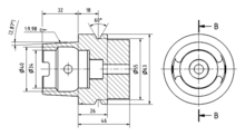
Technical cartoon of a die tool produced past CAD (in Russian).

Copying technical drawings in 1973
Technical drawing, drafting or drawing, is the act and bailiwick of composing drawings that visually communicate how something functions or is constructed.
Technical cartoon is essential for communicating ideas in industry and engineering science. To make the drawings easier to empathize, people utilize familiar symbols, perspectives, units of measurement, note systems, visual styles, and page layout. Together, such conventions plant a visual linguistic communication and aid to ensure that the cartoon is unambiguous and relatively easy to understand. Many of the symbols and principles of technical drawing are codification in an international standard called ISO 128.
The need for precise communication in the preparation of a functional certificate distinguishes technical drawing from the expressive drawing of the visual arts. Artistic drawings are subjectively interpreted; their meanings are multiply determined. Technical drawings are understood to have one intended meaning.[1]
A drafter, draftsperson, or draughtsman is a person who makes a drawing (technical or expressive). A professional drafter who makes technical drawings is sometimes called a drafting technician.
Methods [edit]
Sketching [edit]

Sketch for a government building
A sketch is a quickly executed, freehand drawing that is usually not intended as a finished work. In general, sketching is a quick way to record an idea for subsequently use. Architect'southward sketches primarily serve every bit a way to endeavour out different ideas and establish a composition before a more than finished work, peculiarly when the finished work is expensive and time-consuming.
Architectural sketches, for instance, are a kind of diagrams.[2] These sketches, like metaphors, are used by architects as a means of communication in aiding design collaboration. This tool helps architects to abstract attributes of hypothetical provisional blueprint solutions and summarize their complex patterns, hereby enhancing the design process.[2]
Manual or by instrument [edit]


One-time-fashioned technical drawing instruments

Stencils for lettering technical drawings to DIN standards
The basic drafting procedure is to place a piece of paper (or other material) on a smoothen surface with correct-angle corners and directly sides—typically a drawing board. A sliding straightedge known every bit a T-square is and so placed on one of the sides, allowing it to be slid across the side of the tabular array, and over the surface of the paper.
"Parallel lines" can be fatigued simply past moving the T-square and running a pencil or technical pen along the T-foursquare's border. The T-square is used to hold other devices such as set squares or triangles. In this case, the drafter places one or more triangles of known angles on the T-square—which is itself at right angles to the border of the table—and tin then draw lines at any chosen angle to others on the page. Modern drafting tables come equipped with a drafting machine that is supported on both sides of the table to slide over a big piece of paper. Because it is secured on both sides, lines drawn forth the edge are guaranteed to be parallel.[iii]
In addition, the drafter uses several technical drawing tools to draw curves and circles. Primary amidst these are the compasses, used for drawing unproblematic arcs and circles, and the French bend, for drawing curves. A spline is a rubber coated articulated metal that can be manually bent to most curves.
Drafting templates assistance the drafter with creating recurring objects in a drawing without having to reproduce the object from scratch every fourth dimension. This is particularly useful when using common symbols; i.e. in the context of stagecraft, a lighting designer will draw from the USITT standard library of lighting fixture symbols to indicate the position of a common fixture across multiple positions. Templates are sold commercially past a number of vendors, usually customized to a specific task, but it is also non uncommon for a drafter to create his own templates.
This basic drafting system requires an accurate tabular array and constant attention to the positioning of the tools. A common error is to allow the triangles to button the superlative of the T-square down slightly, thereby throwing off all angles. Even tasks as simple equally drawing 2 angled lines meeting at a point require a number of moves of the T-foursquare and triangles, and in general, drafting can be a fourth dimension-consuming procedure.
A solution to these problems was the introduction of the mechanical "drafting automobile", an application of the pantograph (sometimes referred to incorrectly as a "pentagraph" in these situations) which immune the drafter to have an accurate correct bending at any bespeak on the page quite quickly. These machines often included the ability to modify the angle, thereby removing the demand for the triangles as well.
In addition to the mastery of the mechanics of drawing lines, arcs and circles (and text) onto a slice of paper—with respect to the detailing of concrete objects—the drafting attempt requires a thorough understanding of geometry, trigonometry and spatial comprehension, and in all cases demands precision and accuracy, and attention to particular of high gild.
Although drafting is sometimes accomplished by a project engineer, architect, or shop personnel (such as a machinist), skilled drafters (and/or designers) normally reach the task, and are always in need to some degree.
Computer aided design [edit]
Today, the mechanics of the drafting task accept largely been automated and accelerated through the utilize of computer-aided design systems (CAD).
At that place are 2 types of computer-aided design systems used for the production of technical drawings: ii dimensions ("2nd") and iii dimensions ("3D").

An case of a drawing drafted in AutoCAD
second CAD systems such as AutoCAD or MicroStation supersede the paper cartoon field of study. The lines, circles, arcs, and curves are created within the software. It is downwards to the technical cartoon skill of the user to produce the drawing. There is still much scope for error in the drawing when producing commencement and third angle orthographic projections, auxiliary projections and cantankerous-section views. A 2nd CAD system is only an electronic drawing board. Its greatest forcefulness over direct to paper technical cartoon is in the making of revisions. Whereas in a conventional hand drawn technical cartoon, if a error is found, or a modification is required, a new drawing must be fabricated from scratch, the second CAD system allows a copy of the original to be modified, saving considerable fourth dimension. 2nd CAD systems can be used to create plans for big projects such as buildings and shipping just provide no way to cheque the diverse components volition fit together.
A 3D CAD system (such equally KeyCreator, Autodesk Inventor, or SolidWorks) first produces the geometry of the part; the technical drawing comes from user divers views of that geometry. Any orthographic, projected or sectioned view is created by the software. At that place is no telescopic for error in the product of these views. The primary scope for error comes in setting the parameter of first or third bending projection and displaying the relevant symbol on the technical drawing. 3D CAD allows private parts to be assembled together to represent the final production. Buildings, aircraft, ships, and cars are modeled, assembled, and checked in 3D before technical drawings are released for industry.
Both 2nd and 3D CAD systems can exist used to produce technical drawings for any discipline. The diverse disciplines (electrical, electronic, pneumatic, hydraulic, etc.) have industry recognized symbols to stand for common components.
BS and ISO produce standards to show recommended practices but information technology is up to individuals to produce the drawings to a standard. There is no definitive standard for layout or style. The only standard beyond engineering workshop drawings is in the creation of orthographic projections and cross-section views.
In representing complex, three-dimensional objects in two-dimensional drawings, the objects can exist described by at to the lowest degree one view plus textile thickness annotation, two, iii or every bit many views and sections that are required to testify all features of object.
Applications [edit]
Architecture [edit]

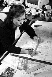
To plan a renovation, this architect takes measurements which he will later enter into his reckoner-aided design system.
The art and design that goes into making buildings is known as architecture. To communicate all aspects of the shape or blueprint, detail drawings are used. In this field, the term plan is often used when referring to the full section view of these drawings as viewed from three feet above finished floor to evidence the locations of doorways, windows, stairwells, etc.[4] Architectural drawings describe and certificate an architect's design.[five]
Applied science [edit]
Applied science can exist a very broad term. Information technology stems from the Latin ingenerare, meaning "to create".[vi] Considering this could apply to everything that humans create, it is given a narrower definition in the context of technical cartoon. Engineering drawings generally deal with mechanical engineered items, such as manufactured parts and equipment.
Engineering drawings are usually created in accordance with standardized conventions for layout, nomenclature, interpretation, advent (such as typefaces and line styles), size, etc.
Its purpose is to accurately and unambiguously capture all the geometric features of a production or a component. The end goal of an engineering science drawing is to convey all the required data that will allow a manufacturer to produce that component.
Software applied science [edit]
Software technology practictioners make employ of diagrams for designing software. Formal standards and modeling languages such as Unified Modeling Linguistic communication (UML) exist but most diagramming happens using informal ad hoc diagrams that illustrate a conceptual model.[7]
Practitioners reported that diagramming helped with analysing requirements,[7] : 539 design, refactoring, documentation, onboarding, communication with stake holders.[8] : 560 Diagrams are often transient or redrawn as required. Redrawn diagrams can acts as a grade of shared understanding in a squad.[8] : 561
[edit]
Technical analogy [edit]

Technical illustration is the utilize of illustration to visually communicate information of a technical nature. Technical illustrations can be component technical drawings or diagrams. The aim of technical illustration is "to generate expressive images that effectively convey certain data via the visual channel to the human observer".[9]
The main purpose of technical illustration is to describe or explain these items to a more than or less nontechnical audience. The visual prototype should be authentic in terms of dimensions and proportions, and should provide "an overall impression of what an object is or does, to heighten the viewer'due south interest and understanding".[10]
According to Viola (2005), "illustrative techniques are often designed in a style that even a person with no technical understanding conspicuously understands the piece of fine art. The utilize of varying line widths to emphasize mass, proximity, and scale helped to brand a simple line drawing more understandable to the lay person. Cantankerous hatching, stippling, and other low brainchild techniques gave greater depth and dimension to the subject matter".[ix]
Cutaway drawing [edit]

A cutaway cartoon is a technical illustration, in which part of the surface of a three-dimensional model is removed in order to show some of the model'due south interior in relation to its exterior.
The purpose of a cutaway drawing is to "allow the viewer to take a await into an otherwise solid opaque object. Instead of letting the inner object shine through the surrounding surface, parts of outside object are merely removed. This produces a visual appearance every bit if someone had cutout a slice of the object or sliced it into parts. Cutaway illustrations avoid ambiguities with respect to spatial ordering, provide a sharp dissimilarity between foreground and background objects, and facilitate a good understanding of spatial ordering".[11]
Technical drawings [edit]
Types [edit]
The 2 types of technical drawings are based on graphical projection.[1] This is used to create an image of a three-dimensional object onto a 2-dimensional surface.
Two-dimensional representation [edit]
Two-dimensional representation uses orthographic projection to create an image where just two of the 3 dimensions of the object are seen.
Three-dimensional representation [edit]
In a iii-dimensional representation, likewise referred to as a pictorial, all three dimensions of an object are visible.
Views [edit]
Multiview [edit]
Multiview is a type of orthographic projection. There are ii conventions for using multiview, first-bending and third-bending. In both cases, the front or main side of the object is the same. First-bending is cartoon the object sides based on where they country. Example, looking at the front side, rotate the object 90 degrees to the right. What is seen will exist drawn to the correct of the forepart side. Tertiary-angle is drawing the object sides based on where they are. Example, looking at the front side, rotate the object 90 degrees to the right. What is seen is actually the left side of the object and will be fatigued to the left of the front side.
Section [edit]
While multiview relates to external surfaces of an object, section views prove an imaginary plane cutting through an object. This is frequently useful to show voids in an object.
Auxiliary [edit]
Auxiliary views utilise an additional projection plane other than the common planes in a multiview. Since the features of an object need to testify the true shape and size of the object, the projection plane must be parallel to the object surface. Therefore, whatever surface that is not in line with the three major centrality needs its own projection airplane to evidence the features correctly.
Pattern [edit]
Patterns, sometimes called developments, testify the size and shape of a flat slice of material needed for later bending or folding into a 3-dimensional shape.[12]
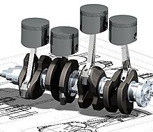
Exploded [edit]

An exploded-view drawing is a technical drawing of an object that shows the human relationship or gild of assembly of the diverse parts.[13] It shows the components of an object slightly separated by distance or suspended in surrounding space in the case of a three-dimensional exploded diagram. An object is represented as if there had been a small controlled explosion emanating from the heart of the object, causing the object's parts to be separated relative distances away from their original locations.
An exploded view drawing (EVD) can testify the intended assembly of mechanical or other parts. In mechanical systems, the component closest to the center is usually assembled first or is the principal part inside which the other parts are assembled. The EVD tin likewise help to represent the disassembly of parts, where those on the outside are usually removed first.[14]
Standards and conventions [edit]
Bones drafting newspaper sizes [edit]
There take been many standard sizes of paper at dissimilar times and in different countries, but today most of the world uses the international standard (A4 and its siblings). North America uses its own sizes.
-

ISO "A series" paper sizes used in well-nigh countries of the earth
-

ANSI paper sizes used in North America
Patent drawing [edit]

The applicant for a patent will be required by law to furnish a drawing of the invention if or when the nature of the case requires a drawing to understand the invention with the job. This drawing must exist filed with the application. This includes practically all inventions except compositions of matter or processes, but a drawing may likewise be useful in the instance of many processes.[13]
The drawing must show every feature of the invention specified in the claims and is required by the patent function rules to be in a particular form. The Office specifies the size of the sheet on which the cartoon is fabricated, the type of newspaper, the margins, and other details relating to the making of the drawing. The reason for specifying the standards in detail is that the drawings are printed and published in a uniform style when the patent issues and the drawings must besides be such that they can be readily understood by persons using the patent descriptions.[xiii]
Sets of technical drawings [edit]
Working drawings for production [edit]
Working drawings are the ready of technical drawings used during the manufacturing phase of a production.[15] In architecture, these include civil drawings, architectural drawings, structural drawings, mechanical systems drawings, electrical drawings, and plumbing drawings.
Assembly drawings [edit]
Assembly drawings show how unlike parts go together, identify those parts by number, and take a parts listing, often referred to every bit a bill of materials.[xvi] In a technical service manual, this blazon of drawing may be referred to equally an exploded view cartoon or diagram. These parts may be used in technology.
As-fitted drawings [edit]
Too chosen As-Built drawings or Equally-made drawings. As-fitted drawings stand for a record of the completed works, literally 'as fitted'. These are based upon the working drawings and updated to reverberate any changes or alterations undertaken during construction or manufacture.[17]
Meet also [edit]
- Circuit diagram
- Linear calibration
- Reprography
- Schematic diagram
- Store drawing
- Technical advice
- Technical lettering
- Specification (technical standard)
References [edit]
- ^ a b Goetsch, David 50.; Chalk, William Due south.; Nelson, John A. (2000). Technical Cartoon. Delmar Technical Graphics Series (Fourth ed.). Albany: Delmar Learning. p. three. ISBN978-0-7668-0531-6. OCLC 39756434.
- ^ a b Richard Boland and Fred Collopy (2004). Managing as designing. Stanford University Press, 2004. ISBN 0-8047-4674-5, p.69.
- ^ Bhatt, N.D. Automobile Drawing. Charotar Publication.
- ^ Jefferis, Alan; Madsen, David (2005), Architectural Drafting and Design (fifth ed.), Clifton Park, NY: Delmar Cengage Learning, ISBN i-4018-6715-4
- ^ Goetsch et al. (2000) p. 792
- ^ Lieu, Dennis K; Sorby, Sheryl (2009), Visualization, Modeling, and Graphics for Engineering Pattern (1st ed.), Clifton Park, NY: Delmar Cengage Learning, ISBN 978-one-4018-4249-nine, pp. i–2
- ^ a b Baltes, Sebastian; Diehl, Stephan (xi Nov 2022). "Sketches and diagrams in practice". Proceedings of the 22nd ACM SIGSOFT International Symposium on Foundations of Software Engineering. FSE 2022. Hong Kong, China: Association for Computing Mechanism: 530–541. arXiv:1706.09172. doi:10.1145/2635868.2635891. ISBN978-i-4503-3056-5.
- ^ a b Cherubini, Mauro; Venolia, Gina; DeLine, Rob; Ko, Amy J. (29 Apr 2007), "Let'south go to the whiteboard: how and why software developers use drawings", Proceedings of the SIGCHI Conference on Human Factors in Computing Systems, New York, NY, Usa: Association for Computing Mechanism, pp. 557–566, doi:10.1145/1240624.1240714, ISBN978-ane-59593-593-nine , retrieved 8 September 2022
- ^ a b Ivan Viola and Meister E. Gröller (2005). "Smart Visibility in Visualization". In: Computational Aesthetics in Graphics, Visualization and Imaging. L. Neumann et al. (Ed.)
- ^ "The Function of the Technical Illustrator in Industry". industriegrafik.com. xv June 2002. Archived from the original on 14 August 2009. Retrieved 15 Feb 2009.
- ^ Diepstraten, J.; Weiskopf, D.; Ertl, T. (2003). "Interactive Cutaway Illustrations" (PDF). vis.uni-stuttgart.de. Archived from the original (PDF) on 16 December 2005. in Brunet, P.; Fellner, D. (eds.). "Eurographics 2003". Eurographics. The Eurographics Association and Blackwell Publishers. 22 (iii).
- ^ Goetsch et al. (2000), p. 341
- ^ a b c "General Data Concerning Patents § i.84 Standards for drawings". USPTO.gov. January 2005. Archived from the original on thirty Jan 2009. Retrieved 13 February 2009.
- ^ Michael E. Brumbach, Jeffrey A. Clade (2003). Industrial Maintenance. Cengage Learning, 2003 ISBN 0-7668-2695-three, p.65
- ^ Ralph Due west. Liebing (1999). Architectural working drawings. John Wiley and Sons, 1999. ISBN 0-471-34876-7.
- ^ Goetsch et al. (2000), p. 613
- ^ "as-congenital drawings". BusinessDictionary.com. 26 December 2022. Archived from the original on 3 Dec 2022. Retrieved 1 January 2022.
Further reading [edit]
- Peter J. Booker (1963). A History of Applied science Drawing. London: Northgate.
- Franz Maria Feldhaus (1963). The History of Technical Drawing
- Wolfgang Lefèvre ed. (2004). Picturing Machines 1400–1700: How technical drawings shaped early engineering exercise. MIT Press, 2004. ISBN 0-262-12269-3
External links [edit]
- Historical technical diagrams and drawings at NASA.
- A history of CAD
- Drafting Standards

Source: https://en.wikipedia.org/wiki/Technical_drawing
Posted by: dewsfrept1991.blogspot.com
0 Response to "Michael Is Using A Drawing Program To Complete A Construction. Which Construction Is He Completing?"
Post a Comment